MONEC or Apple - who copied from whom?
Innovations and Patents from 1999 to 2002
Device Generation 1 - 2 of IPads
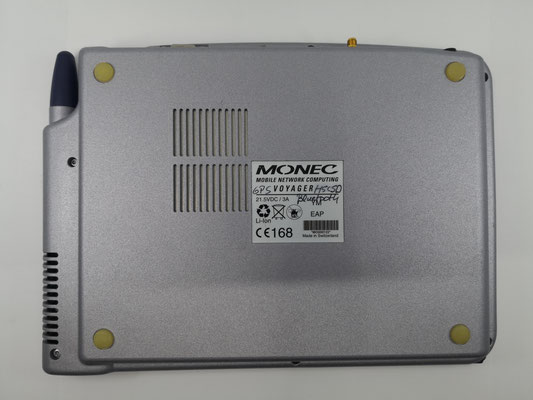
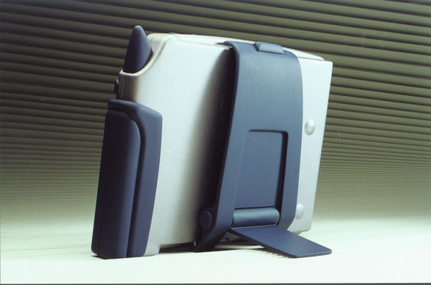
1. Generation Voyager from 1998 by MONEC
(MONEC is a company founded by Theodor Heutschi)
Inventor Theodor Heutschi, Patent no. PCT/CH99/00084, WO99/44144, US 6.335.678 B1
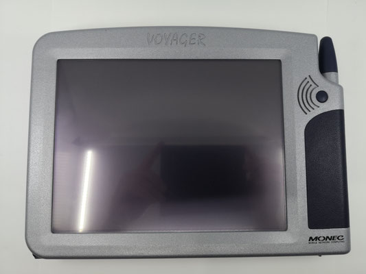
2. Generation Voyager from 1999 by MONEC
Inventor Theodor Heutschi, Patent no. PCT/CH99/00084, WO99/44144, US 6.335.678 B1
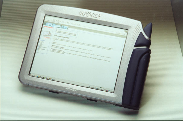
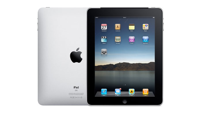
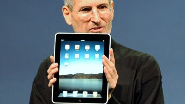
IPad Apple from 2010 market launch
MONEC Voyager 1998 - Apple IPad 2010 - Who copied from whom?
New Generation of Mobile Multimedia Device by MONEC
A new generation of mobile multimedia terminals Mobile devices such as cellular phones and personal digital assistants are becoming more and more powerful, permitting an ever-broader range of functions and applications. Today’s communication terminals and wireless internet devices are limited, however, by their small visual displays. Office, internet and multimedia applications (sound, pictures and video) and gaming systems all use a well-sized quality screen. The problem is that a large screen also means a large device, high weight and high costs. What is needed – and is virtually assured of sound market success – is a device with the size of a cellular phone, the power of a personal computer and a virtual screen offering the dimensions and quality of a large desktop monitor. The product for which this patent application is being submitted is designed to resolve the current conflict between the small size of today’s mobile devices and the desire to view digital content on a full-format display. A virtual retinal display or VRD system, such as a small lens integrated into the mobile terminal, will scan the photons containing the image data directly onto the retina of the user’s eye. As illustrated in Figure 1, a photon source such as a laser diode or a light-emitting diode (LED) generates a beam of light (the photon source may actually be three such sources if a colour image is to be rendered). The beam of light is intensity-modulated by a modulation unit to match the intensity of the image being generated. A beam scanner then receives the modulated signal and scans it across the retina using a particular scan pattern. The terminal may consist of one VRD system or of two such systems for the projection of stereo images into the user’s eyes. Figure 1 The system can be fully integrated into a cellular phone either as a two-dimensional image system or as a stereo image system. An autonomous VRD system which can be docked onto an existing cellular phone like today’s camera module will also be available. The new system should represent a breakthrough for mobile terminals, offering: - small size with high resolution and high quality - low power consumption - a low price - stereo images and video in colour and - no irritation in sunlight. Research and development The kind of VRD system described above can be integrated into a cellular phone according to Professor M. Menozzi of the Swiss Federal Institute of Technology in Zurich, a specialist in the field. Its development by a team of specialists is expected to take about three years. I will be contributing to this project: - my ownership of the international patent application (patent pending) - my patent knowledge from the USA and Europe (as an inventor of US patents) - my extensive experience in mobile multimedia and communication devices and - my extensive experience in telecommunications technology.
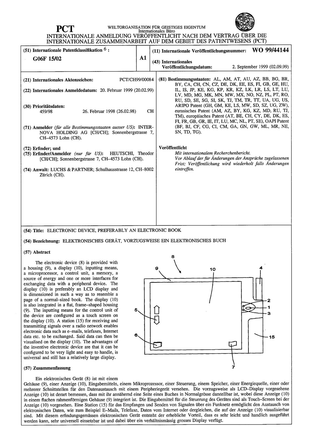
Electronic device, in particular a mobile multimedia communication device
The invention relates to an electronic device, in particular a mobile multimedia communication device, according to the generic term of claim 1. Such devices, e.g. mobile phones, PDAs (personal digital assistants), MP3 players, etc., are known in a wide variety of designs and are available on the market. These devices are equipped with a display for text and images, which consists of an LCD (liquid crystal display). Due to its dimensions, this only allows for moderate to poor image quality. It is therefore not possible, especially with small devices with small screen sizes, to view cinema films, videos or a photo album in acceptable quality on the displays. If larger displays are used, the device not only becomes heavier and more bulky, but also more expensive and requires more power. The present invention is based on the task of creating a device of the type mentioned above that guarantees excellent image quality even with smaller device sizes, is inexpensive to manufacture and has low power consumption, and can be used as a universal, mobile communication device.
According to the invention, this task is solved by an electronic device with the features of claim 1. Further preferred embodiments of the device according to the invention are the subject of the dependent claims. In that at least one VRD (Virtual Retinal Display) system is provided for processing an image or data source and projecting it in the form of laser beams onto the retina of the device user, and the device has a station designed for audio, video and data communication for receiving and transmitting signals via a radio network or other transmission devices, whereby the signals can be exchanged via the Bluetooth, Wireless LAN, GSM, GPRS, EDGE, UMTS, DAB system, the 4G or 5G system or via any telephone cable, radio or satellite network, a cost-effective device is created that can provide excellent image quality with high image resolution, in particular three-dimensional colour image resolution, that can be designed to be lightweight and easy to handle, and can therefore be used as a universal multimedia communication device anytime, anywhere.
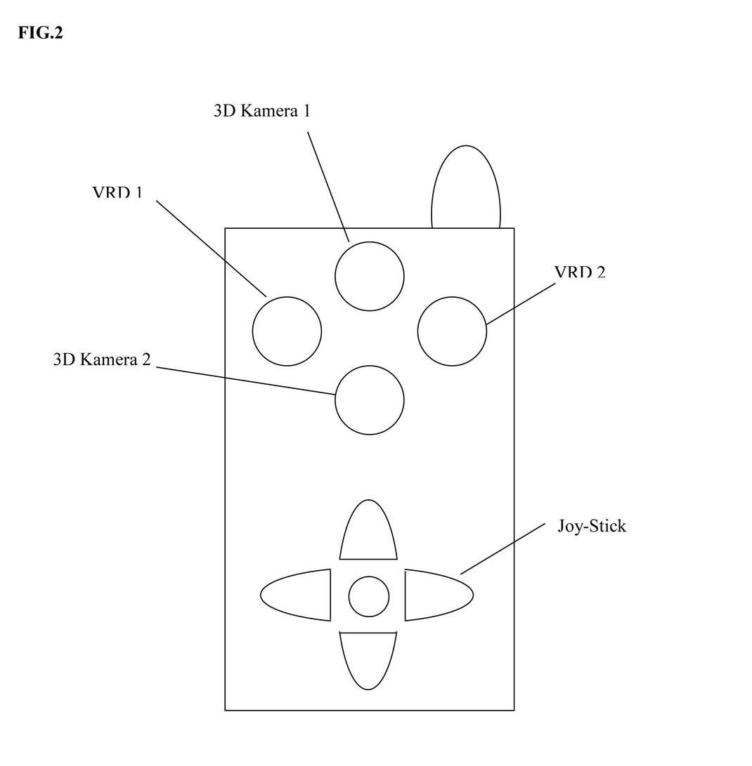
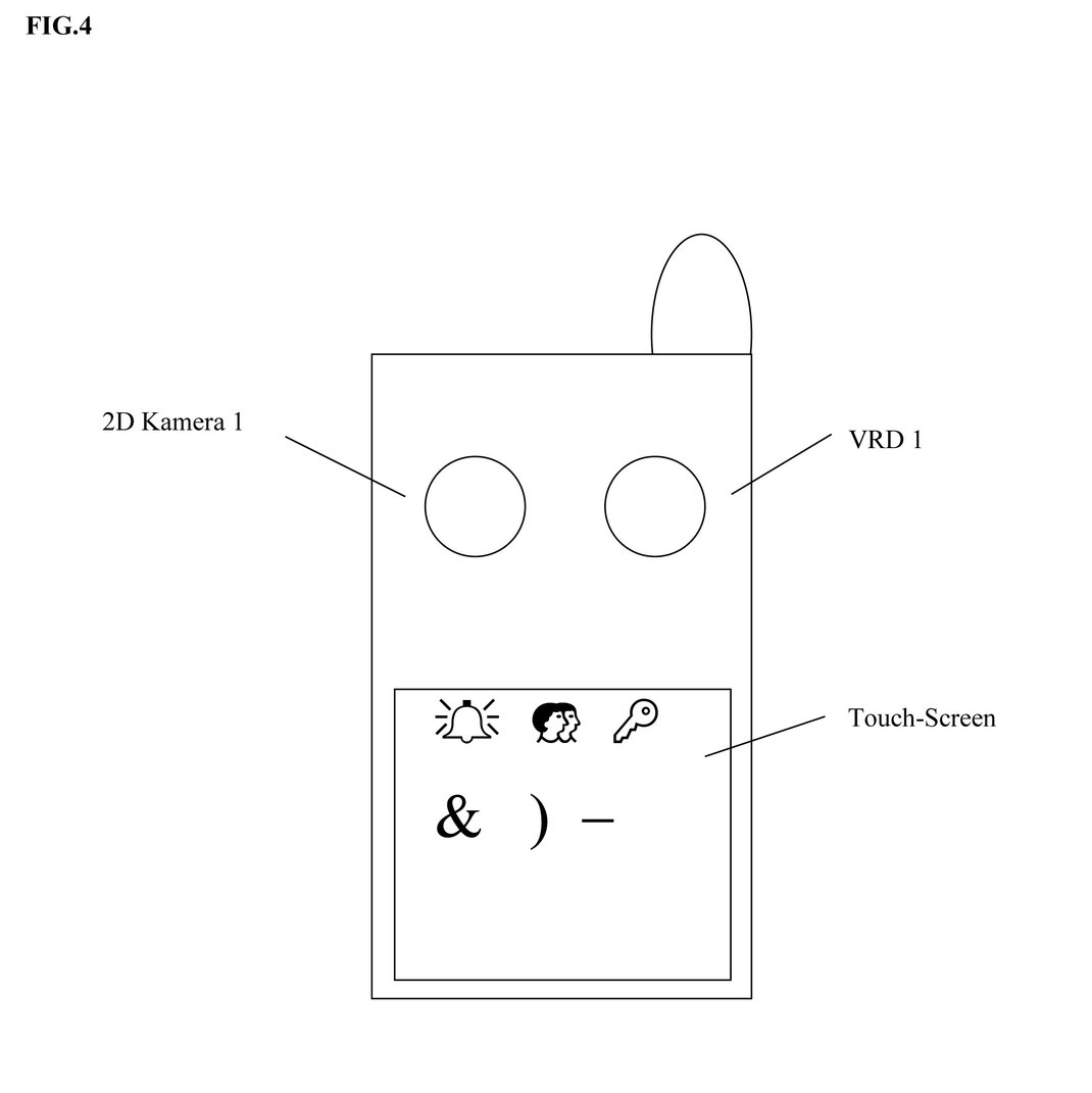
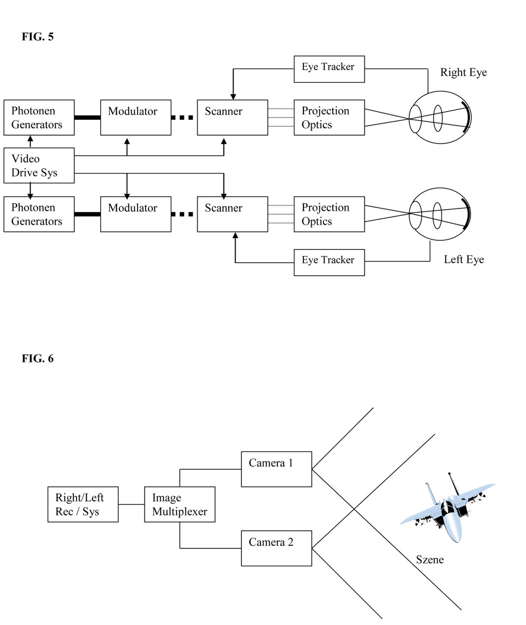
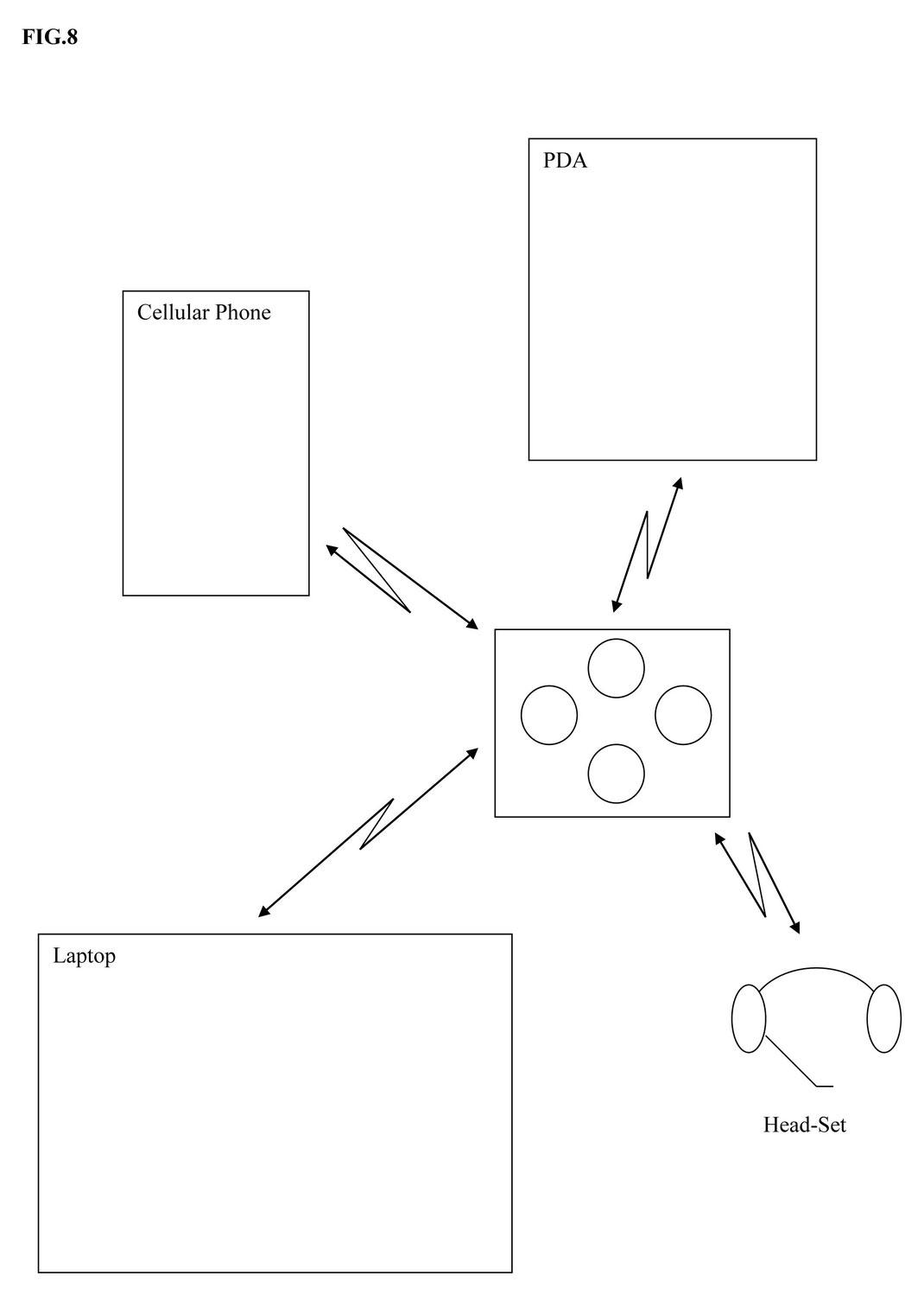
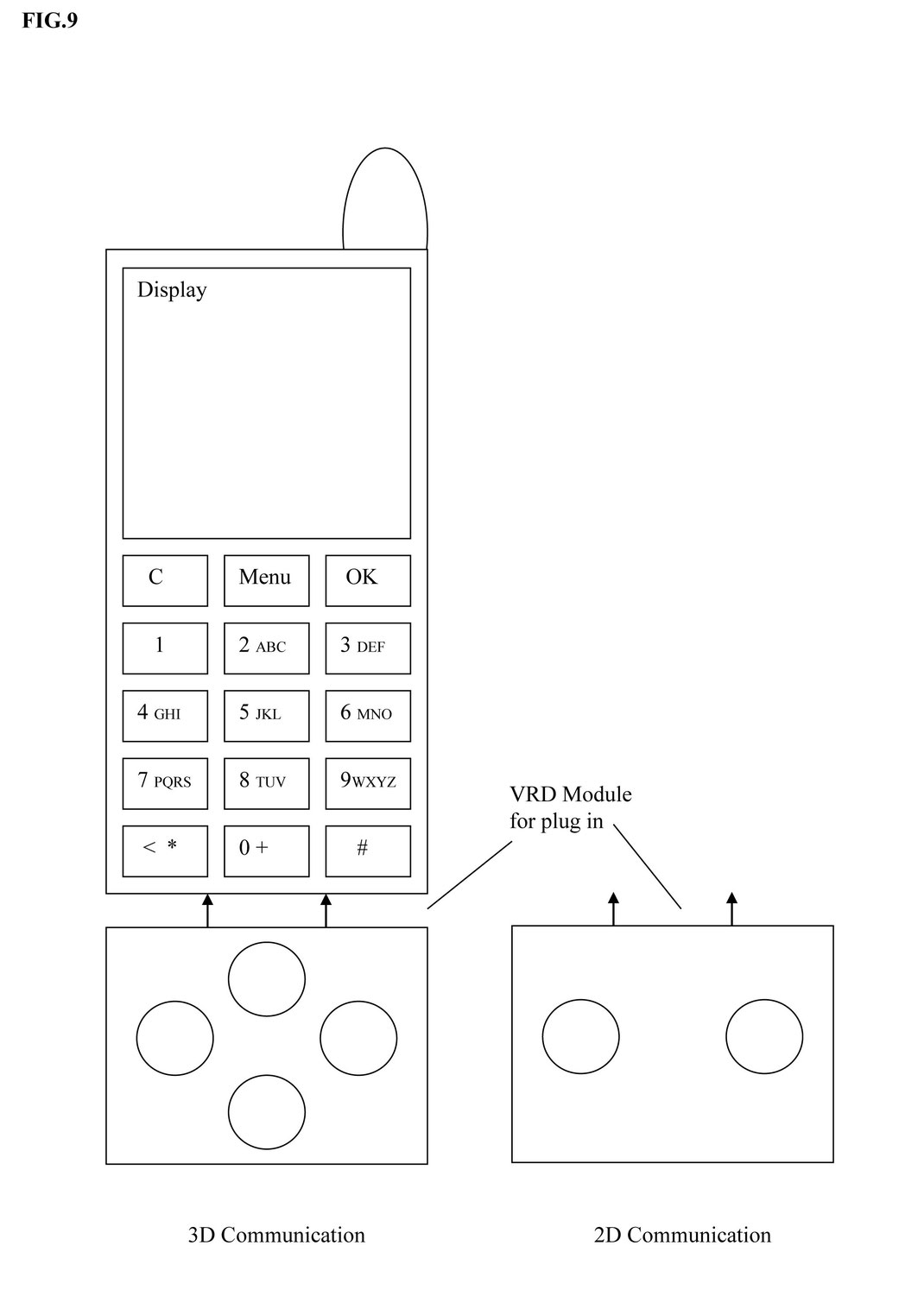
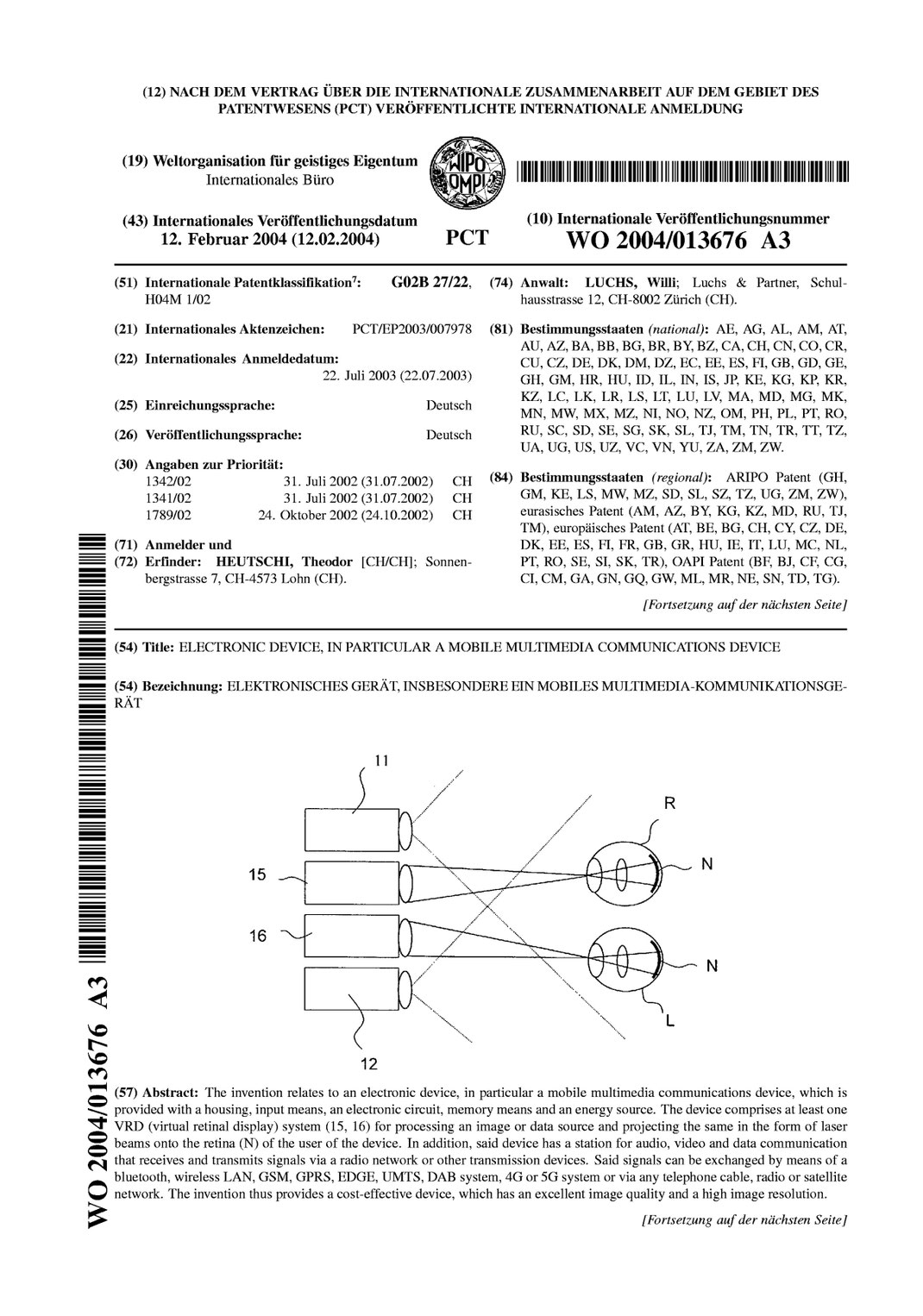
The invention is explained in more detail below with reference to the drawings. The following figures show purely schematic representations: Fig. 1 shows a principle of image recording and image transmission intended for a communication device according to the invention; Fig. 2 shows a block diagram of image recording; Fig. 3 shows a first embodiment of a communication device; Fig. 4 shows a second embodiment of a communication device; Fig. 5 shows a block diagram of image transmission; Fig. 6 shows a third embodiment of a communication device; Fig. 7 shows a block diagram of the communication device according to the invention; Fig. 8 shows a self-sufficient multimedia module connected to several peripheral devices; and Fig. 9 shows two multimedia modules that can be connected to a device. Fig. 1 schematically shows a principle used in the device according to the invention for transmitting three-dimensional images. Two electronic cameras (preferably CCD cameras) 11, 12 are used for image capture, as also indicated in Fig. 2, which capture a subject, e.g. the aircraft indicated in Fig. 2, from two different angles. The two partial images can be captured with a vertical or horizontal shift. This means that the two cameras 11, 12 can be arranged vertically or horizontally. The images captured by the cameras 11, 12 (stereoscopic half-images) are recorded and displayed in real time or at a later point in time via a VRD (virtual retinal display) system. If two VRD systems 15, 16 project the synchronised images captured by the two electronic cameras 11, 12 onto each of the viewer's eyes L and R, three-dimensional images (black-and-white or colour images) with high image resolution can be conveyed. With the aid of special recording techniques, three-dimensional image effects can also be achieved with a single camera. One camera is sufficient for two-dimensional image transmission. If only a two-dimensional image is required, two users can even view the same image information simultaneously if a laser beam is projected onto the eyes of both users via one VRD system each. With the aid of special technical means, however, it is also possible to convey three-dimensional image impressions with only one VRD system. More than two cameras could also be used to convey three-dimensional images. According to the invention, small, handy electronic communication devices can also be equipped with at least one VRD system 15 or 16 for processing an image or data source and projecting it onto the user's retina, thereby providing excellent image quality with high image resolution, in particular three-dimensional colour image resolution, which is completely independent of the size of the device. This enables the creation of a mobile, universally applicable communication device which is intended for audio, video and data communication between two or more users and/or between the user and external computer systems and/or peripheral devices. However, it can also be a so-called multimedia communication device that combines a video player, music player, PDA (personal digital assistant), laptop and game console in one device. Audio, video and data communication takes place via one or more communication modules integrated into the device. Data transmission preferably takes place via a radio network such as Bluetooth, wireless LAN, GSM (Global System for Mobile Communication), GPRS (General Packet Radio System), EDGE (Enhanced Data rates for GSM Evolution), UMTS (Universal Mobile Telecommunications System), DAB (Digital Audio Broadcasting), via so-called 4G (fourth generation) or 5G (fifth generation) or via any other radio system with a transmission speed of 20-100 Mb/s, or by other transmission devices – for example, via a telephone cable or satellite network. The device can be used worldwide and is capable of using multi-band (multiple frequency spectrums such as 900/1800/1900 MHz or other international frequencies). The device can be connected directly to a monitor, mouse, keyboard and printer at home or in the office, thus turning it into a work computer. Alternatively, the device can be converted into a portable laptop computer by connecting a keyboard. In the car, the device can serve as a navigation system. This means you no longer have to deal with a multitude of electronic devices – PC, laptop, PDA, mobile phone, video and music players, etc. – and constantly check where your data is stored. Everything merges into a personal companion that contains all your information and allows you to access the Internet and local networks anywhere and anytime. With a wide range of communication and multimedia functions, the device can also be used as an online game console in a particularly advantageous way. Two or more online game participants can also talk to each other via live video conferencing, for example, and form different game teams worldwide. However, two or more game participants could also be connected via the Internet, either in the same room or separated from each other geographically. An example of such a device 1 is shown schematically in Fig. 3. Device 1 has a housing 2 made of plastic, metal, a metal alloy or a sintered material so that it is lightweight, stable and inexpensive to manufacture and allows heat dissipation. EMC (electromagnetic compatibility) and ESD (electrostatic discharge) regulations are taken into account when selecting the material. Device 1 is equipped with the two cameras 11, 12 mentioned above and with the two VRD systems 15, 16, which enable three-dimensional image transmission. In this embodiment, cameras 11, 12 are arranged vertically one above the other, and VRD systems 15, 16 are arranged horizontally next to each other. The fields recorded by cameras 11, 12 are stored via an image multiplexer 13a (see block diagram in Fig. 2) on a video recorder or a video buffer 13b for further processing. The video signals can be forwarded to another device in real time via radio or cable network. Fig. 5 shows a block diagram of the dual VRD system present in device 1. Each VRD system 15, 16 has a photogenerator 17, 18 and a modulator 19, 20. The photogenerators 17, 18 generate photons that are modulated with video information in the modulators 19, 20. The respective modulator 19, 20 aligns the photons horizontally. The modulated photons are assembled vertically into a photon grid with the aid of a scanner 21, 22. The photons aligned to form a grid are projected directly onto the retina N of the device user via a projection optic 23, 24, which conveys the impression of an upright virtual image. For black-and-white images, one photon generator 17, 18 per eye is sufficient. For colour images, the photon generator 17, 18 houses three individual generators for red, green and yellow or blue light, which project RGY (red-green-yellow) or RGB (red-green-blue) modulated video signals directly onto the user's eye. In order to generate the most realistic, three-dimensional image possible, a VRD system 15, 16 is provided for each eye. Each VRD system 15, 16 synchronously transmits a field image to the retina N of the corresponding eye L, R, thus conveying a spatial image. A video drive system 13c demultiplexes the video signal and assigns the correct fields to the right and left VRD systems 15, 16. In addition, the video drive system 13c sends colour information to the photon generators 17, 18, horizontal and vertical synchronisation signals to the modulators 19, 20 and to the scanners 23, 24. In addition, a so-called eye-tracking system (i.e. a system for determining the position of the eye) 25, 26 can be provided for each eye L, R. For example, the exact position of the eye can be determined using an infrared beam. The position data is fed to the corresponding scanner 21, 22, which then makes the necessary correction so that the photon beam is always placed exactly on the pupil. The housing 2 of the device 1 accommodates an electronic circuit, storage media and an energy source in a manner not shown in Fig. 3 but mentioned below in connection with Fig. 7. The energy source can be formed, for example, by a battery, a solar cell generator, thermoelectric generators or a mini fuel cell and can be rechargeable. Solid-state memory (chip memory) is provided as working, data and programme memory. For capacity and cost reasons, device 1 can also be equipped with a hard disk. Biological and nanomechanical memory could also be used. Device 1 is also equipped with an antenna 27a (however, this could also be integrated invisibly into the housing 2). A so-called joystick 3 and buttons are provided as input devices. Fig. 4 shows another variant of a communication device 1' according to the invention, which essentially corresponds to device 1 according to Fig. 3 and also ensures three-dimensional image transmission. In this embodiment, the cameras 11, 12 are arranged horizontally next to each other and the VRD systems 15, 16 are arranged vertically one above the other. A keyboard 4, as in a mobile phone, is provided as an input device. Fig. 6 shows a third embodiment of a device 1’’ according to the invention, which is intended solely for two-dimensional image transmission and is therefore equipped only with a VRD system 15 and a camera 11. The device 1’’ has a sensor screen (touch screen) as an input device. 5 as an input device. However, a proximity switch that can be combined with a display could also be used as an input device. This switch could advantageously be inductive or capacitive, or switch by means of sound wave or infrared scanning, and could be activated by a magnet that can only be operated by the person who possesses the corresponding part and knows the corresponding functions. An acoustic signal can also be provided as an input device, whereby the device can be tuned to a specific frequency, frequency spectrum or voice. Brain waves could also serve as an input device, whereby one or more detectors are attached to defined locations on or around the head and the input command can be issued depending on the thoughts. In the office or at home, the device can be operated like a laptop or PC with a keyboard and mouse. All peripheral devices can be operated via cable or wirelessly using radio technologies such as Bluetooth, infrared, wireless LAN or Dect. Fig. 7 shows a block diagram of a possible device according to the invention, with a possible configuration of the overall system. Various modules are connected to a bus system 30. For stereo image capture, the two cameras 11, 12 mentioned above are connected to the bus system 30 via a control unit 31. For three-dimensional image display on the retina, the two VRD systems 15, 16 are connected to the bus system 30 via a control unit 32. The aforementioned electronic circuit (designated 35 in Fig. 7) advantageously comprises two separate processors 36, 37 (central processing units, CPUs) equipped with their own memory modules 38a (ROM), 38b (RAM) and 39a (ROM), 39b (RAM), respectively. The two processors 36, 37 can be operated simultaneously with different operating systems so that the advantages of a pocket operating system (such as Windows CE or Plam OS) and a PC operating system (such as Windows XP, Mac OS, Linux) can be utilised. Processor 36 with memory modules 38a, 38b and a real-time clock 33 (RTC) is intended for the PC operating system. Processor 37 with memory modules 39a, 39b and a real-time clock 34 is responsible for the pocket operating system. Both systems run independently of each other. A resource manager 40 allocates the system resources to the correct processor 36 or 37 depending on the priorities and user specifications. If, for example, a telephone call needs to be made or a stored address with the corresponding telephone number needs to be found, the user can start their pocket operating system (processor 37) and make the call immediately. but also start the PC operating system (processor 36) during the phone call so that they can save time and start working on the PC (e.g. word processing or spreadsheets) immediately after the phone call. The selective use of different operating systems and processors in a single device significantly increases user acceptance of so-called ‘all-in-one’ systems, reduces power consumption and thus extends operating time many times over. However, the device could also be equipped with only one processor and run on a single operating system, or contain more than two processors for more than two operating systems. The preferred rechargeable energy source is designated 41 in Fig. 7. It may consist of a battery, a charger, a solar cell generator, a mini fuel cell or a thermoelectric generator. The overall system may also have a hard disk, DVD, CD, MP3 or other music player (reference number 42 in Fig. 7) with a corresponding control unit 43. Furthermore, one or more SIM card or smart card readers 45 are operatively connected to the bus system 30 via a control unit 46. The SIM (subscriber identity module) card is a credit card-sized identification card for subscribers to a mobile phone service (GSM, GPRS, UMTS, etc.) and is generally referred to as a ‘chip card’ or ‘smart card’. It contains a chip with subscriber-relevant data and algorithms as well as the subscriber's access authorisation to the mobile phone network. Complex keys and algorithms for security systems can also be stored on the SIM card or chip. Due to the constant miniaturisation of devices, in most cases only the chip – removed from the SIM card – is installed in the device. The overall system also contains a receiving and transmitting station 27, which is formed by one or more radio modules for the wireless transmission of data and information and is connected to the bus system 30 via a control unit 47. The data can be transmitted, for example, over short distances via Bluetooth, wireless LAN and over long distances via GPRS, UMTS, DAB, 4G or 5G, or via satellite. An audio interface 49 for a microphone 50 and for loudspeakers 51 is coupled to the radio module and the bus system 30. The receiving and transmitting station 27 could also be formed by an infrared module for data transmission. For the reception of satellite data and for position determination, a position determination system 53 is connected to the bus system via a control unit 54. This positioning system 53 allows route navigation and location-based services to be used via terrestrial radio antennas or satellite systems. The device can also be equipped with a conventional LCD display 55 connected to the bus system 30 via a control unit 56. As already mentioned, a joystick 3 and/or a keyboard 4 or a touch screen 5, connected to the bus system 30 via a control unit 58, can be used for input. Fig. 8 shows a schematic diagram of a module 10 designed to transmit three-dimensional images, equipped with the two cameras 11, 12 and the two VRD systems 15, 16, which is designed as an independent unit and functions autonomously. The module 10 can exchange video signals and data with various peripheral devices, such as an external headphone set 60, a PDA (personal digital assistant), a cellular phone 62, a laptop 63 or other devices, via a radio or cable network. As indicated in Fig. 9, a module 10' designed to transmit three-dimensional images and equipped with the two cameras 11, 12 and the two VRD systems 15, 16 can be connected to or attached to a device 1a, e.g. a cellular phone or a PDA.
The use of the VRD method in the electronic devices according to the invention has the advantage that users with visual impairments (short-sightedness or long-sightedness) or with corrective lenses do not need glasses or other visual aids to read conventional screens or displays, as the projection takes place directly on the retina (the VRD method is self-correcting, so to speak). A further advantage is the relatively low cost and, compared to conventional displays, low Power consumption. An extremely low laser power (e.g. less than 100 nW) of coherent radiation is sufficient to produce a very bright image. This advantage is particularly striking in strong sunlight. While LCD displays are difficult or impossible to read even in normal sunlight, VRD systems produce razor-sharp images on the retina even in the strongest sunlight. The invention is sufficiently illustrated by the above embodiments. However, it could also be illustrated in other variants. The device according to the invention is particularly suitable for use in a vehicle, be it a car, truck, motorbike or similar, in which it can be used as a mobile device, either removable or fixed. When in use, the driver can concentrate on the road while the device simultaneously projects a virtually transparent image into their eyes.
VRD Virtual Reality Display
A new generation of mobile multimedia terminals
Mobile devices such as cellular phones and personal digital assistants are becoming more and more powerful, permitting an ever-broader range of functions and applications. Today’s communication terminals and wireless internet devices are limited, however, by their small visual displays. Office, internet and multimedia applications (sound, pictures and video) and gaming systems all use a well-sized quality screen. The problem is that a large screen also means a large device, high weight and high costs. What is needed – and is virtually assured of sound market success – is a device with the size of a cellular phone, the power of a personal computer and a virtual screen offering the dimensions and quality of a large desktop monitor.
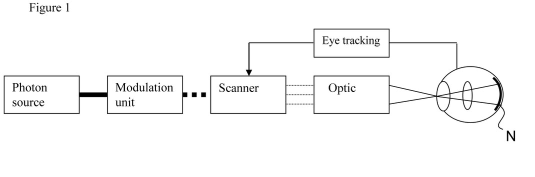
The product for which this patent application is being submitted is designed to resolve the current conflict between the small size of today’s mobile devices and the desire to view digital content on a full-format display. A virtual retinal display or VRD system, such as a small lens integrated into the mobile terminal, will scan the photons containing the image data directly onto the retina of the user’s eye. As illustrated in Figure 1, a photon source such as a laser diode or a light-emitting diode (LED) generates a beam of light (the photon source may actually be three such sources if a colour image is to be rendered). The beam of light is intensity-modulated by a modulation unit to match the intensity of the image being generated. A beam scanner then receives the modulated signal and scans it across the retina using a particular scan pattern. The terminal may consist of one VRD system or of two such systems for the projection of stereo images into the user’s eyes.
The system can be fully integrated into a cellular phone either as a two-dimensional image system or as a stereo image system. An autonomous VRD system which can be docked onto an existing cellular phone like today’s camera module will also be available.
The new system should represent a breakthrough for mobile terminals, offering:
- small size with high resolution and high quality
- low power consumption
- a low price
- stereo images and video in colour and
- no irritation in sunlight.
Research and development
The kind of VRD system described above can be integrated into a cellular phone according to Professor M. Menozzi of the Swiss Federal Institute of Technology in Zurich, a specialist in the field. Its development by a team of specialists is expected to take about three years.
Contributing to this project:
- my ownership of the international patent application (patent pending)
- my patent knowledge from the USA and Europe (as an inventor of US patents)
- my extensive experience in mobile multimedia and communication devices and
- my extensive experience in telecommunications technology.
3D-Multimedia Communication
The invention relates to an electronic device, preferably a mobile multimedia communication device, according to the generic term of claim 1. In today's mobile phones, personal digital assistants (PDAs) and MP3 players, the display for text and images consists of an LCD display, which, due to its size, only allows for moderate to poor image quality. The screen size is in turn dependent on the form factor of the device. The smaller the device is built, the smaller the built-in screen will be. It is therefore not possible with today's devices to play movies, video conferences or photo albums in acceptable quality on the small displays. If larger displays are used, the end product not only becomes heavier and bulkier, but also more expensive and requires more power. It is a detour when people stare at a monitor on a PC or television. They already have two powerful screens by nature. They are located at the back of the eyes and are called the retina. The eye lens projects far more image information onto them than any cinema screen can display. Their usable area is only a few square centimetres. The simplest solution would be to transmit computer data or TV images directly to the retina using harmless laser beams, instead of displaying them on an artificial display just so that the human eye can read the information there. Most patent specifications, such as US 5,903,397 and US 6,120,461, are based on special glasses with built-in devices that convert video information into photons, control their intensity and beam them through the pupil onto the retina at several hundred million pixels per second. The lasers scan the retina line by line, like the electron beam of a traditional Braun tube. This produces very high-resolution images that appear to the viewer as if they were looking at a cinema screen. If two VRD systems are used to project synchronised images onto each of the viewer's eyes, true three-dimensional video images can be achieved. Experience shows that such special glasses or head-mounted systems are very uncomfortable and distracting for the user. Furthermore, user acceptance suffers considerably from the compromised aesthetics and freedom of movement. In contrast, the present invention was based on the task of creating a mobile electronic device that is as small as possible and enables maximum 3D colour image resolution, independent of the form factor of the device. The electronic device is intended to be a universal communication device that the user can use anytime, anywhere. According to the invention, the task is solved according to the characteristics of claim 1. This inventive electronic device offers the considerable advantage that it can be made very light and handy, is very versatile and has excellent 3D colour image resolution. The dimensions of this device are no longer dependent on the form factor and resolution of the display. If only 2D image resolution is required in terms of image quality, two users can even view the same image information at the same time. Each VRD system projects a photon beam onto the eyes of the two users.
Today's mobile phones and personal digital assistants only have conventional 2D cameras, if any. In order for users to view images in 3D, they must first be recorded with special 3D cameras. One of the few methods that does not require glasses to view 3D images is the so-called autostereoscopic method. Here, depth perception is created by ‘replacing distant objects with closer ones’. More specifically, this means that the impression of depth in this method is created by the fact that distant objects – as in real perception – appear to hardly change their location when viewed alternately by the left and right eyes, while nearby objects appear to change their location abruptly to the right or left. If the screen delivers these two perspectives to the brain at a certain optimal frequency, the two-dimensional image takes on a sense of depth. The subject is captured from two different angles. The two partial images can be captured with vertical or horizontal displacement. This means that the two video cameras can be arranged vertically or horizontally. Whereas users with vision correction previously needed visual aids or glasses to read a conventional screen, the VRD method has a self-correcting effect for the visually impaired (short-sighted or long-sighted), as the photon beam projects the images directly onto the retina. Another advantage of the VRD method is its relatively low cost and low power consumption compared to conventional displays. An extremely low laser power (79 nW) of coherent radiation is required to produce a very bright image. This advantage is particularly striking in strong sunlight. While LCD displays are difficult or impossible to read even in normal sunlight, VRD systems produce razor-sharp images on the retina even in the strongest sunlight. The laser beam is automatically positioned correctly on the retina at all times via the so-called eye-tracking system, which can follow the user's eye movements. Audio, video and data communication between two or more users or external computer systems and peripheral devices is carried out via one or more integrated communication modules. Data transmission can preferably be carried out via a wireless network such as Bluetooth, Wireless Lan, GSM (Global System for Mobile Communication), GPRS (General Packet Radio System), EDGE (Enhanced Data rates for GSM Evolution), UMTS (Universal Mobile Telecommunications System) and via so-called 4G (fourth generation) or 5G (fifth generation) systems with 20-100 Mb/s transmission speed or by other transmission devices, e.g. satellites. The electronic device is equipped with one or more SIM card readers (subscriber identity module). The SIM card is a credit card-sized identification card for subscribers to a GSM mobile phone service (GSM, GPRS, UMTS, etc.) and is generally referred to as a ‘chip card’ or ‘smart card’. These cards are available for car phones and, in a smaller version, for mobile phones. Due to the constant miniaturisation of mobile phones, most mobile phones now only use the chip. For this purpose, it can be removed from the SIM card and installed in the mobile phone. The SIM card or its chip contains subscriber-related data and algorithms as well as access authorisation to the network. Among other things, the SIM card contains the international subscriber number IMSI (international mobile subscriber identity), the international identification number for the mobile device IMEI (international mobile equipment identity), the
authentication key (KI) and some other data. With the SIM card for the mobile network, the subscriber identifies themselves with their mobile phone number, the MSISDN (mobile subscriber ISDN). With the help of authentication, the network ensures that the subscriber is actually an authorised mobile subscriber. The authentication process is carried out in parallel on the SIM card and in the network, and the results are compared. If the results match, the subscriber's authenticity is guaranteed. After the registration procedure, the subscriber can make calls with any GSM phone within their operator's coverage area. In addition,participants can be reached at their personal telephone number both at home and abroad. Complex keys and algorithms for security systems can also be stored on a SIM card or smart card. An integrated positioning system, such as location determination via terrestrial radio antennas or satellite systems, enables route navigation and location-based services to be used. In addition to mobile 3D communication, the device can also store thousands of MP3 songs, play video films and manage addresses and data. The device is so powerful that it can easily handle demanding operating systems such as Windows XP, Mac OS and Linux, as well as pocket PC operating systems such as Windows CE and Plam OS. Furthermore, all user programmes based on these operating systems can also be installed. The device can be connected directly to a monitor, mouse, keyboard and printer at home or in the office, transforming this mobile all-rounder into a fully-fledged work computer. Or you can simply connect the keyboard to turn it into a laptop. The same multimedia device is a PDA and an MP3 or video player in your jacket pocket, a PC on your office desk, a portable laptop computer in your briefcase, a 3D mobile phone in your hand and a navigation system in your car. A major drawback when using PC operating systems such as Windows XP, Windows 2000 or Mac OS is the sometimes very long start-up procedure of the operating system. It can sometimes take minutes for a personal computer to be ready for use. When using word processing, spreadsheet and graphics programs, laptop users have become accustomed to endless waiting. This is not the case when making phone calls or sending text messages. If a user wants to use time-critical applications such as making phone calls, checking or sending text messages or emails, searching for addresses or saving phone numbers, the device must be ready for use immediately. The operating system of such communication devices is stored directly in the BIOS or ROM and can therefore be started within fractions of a second. In order to take advantage of the benefits of a Pocket PC operating system and a PC operating system, the invention provides for the integration of two separate CPUs (central processing units) with memory modules into the electronic device. The two CPUs can be operated simultaneously with different operating systems. If a phone call needs to be made or a stored address with the corresponding phone number is needed, the user can simply start their pocket PC operating system and make the call immediately. If they want to check a spreadsheet after the call, they can start the PC operating system while still on the phone, saving time and allowing them to start working immediately after the call. The selective use of different operating systems and processors in a single device significantly increases user acceptance of all-in-one systems, reduces power consumption and extends operating time many times over.
With a wide range of communication and multimedia functions, the electronic device can be used very effectively as an online gaming console. Email, chat and play with one or more partners anywhere and anytime via a high-speed wireless connection to the internet. It is quite conceivable that online gamers will also be able to talk to each other via live video conferencing, forming gaming teams from around the world. Compared to conventional PDAs or laptops, the invention does not need to synchronise emails, addresses and appointments with stationary workstations. They are already these workstations. Thanks to their large storage capacity and state-of-the-art processors, they offer many times more storage space and computing speed than today's pocket computers when you are on the move. This means that users no longer have to deal with a multitude of electronic devices – office and home PCs, laptops, PDAs, mobile phones, video and music players – and constantly check where which data is stored. Everything merges into a personal companion that contains all programmes and information and provides access to the Internet and local networks anywhere and anytime via the integrated radio module. The 3D multimedia device consists of a housing, a VRD module, a camera module, input devices, an electronic circuit, storage media, a receiver and transmitter, and a power source that can be charged using solar cells, thermoelectric generators or mini fuel cells, for example. The housing is intended to be made of plastic, metal, a metal alloy or a sintered material so that it is lightweight, stable and inexpensive to manufacture and allows for good heat dissipation. The EMC (electromagnetic compatibility) and ESD (electrostatic discharge) regulations are complied with through the selection of suitable materials. Solid-state memory (chip memory) is intended for use as working, data and programme memory. For capacity and cost reasons, the device can also be equipped with a hard disk. The device can also be equipped with biological memory. It is very advantageous for the electronic device to be equipped with loudspeakers and a microphone. If the user wishes to communicate privately and without disturbance, an external headphone and microphone set can be connected to the device via cable or radio, e.g. Bluetooth. Buttons, joysticks, touch screens or proximity switches can be provided as input devices, whereby the latter advantageously operate inductively or capacitively, or switch by means of sound wave or infrared scanning, and can be combined with the display by means of a magnet that can only be operated by the person who owns the corresponding part and knows the functions. An acoustic signal can also be provided as an input device, whereby the device can be tuned to a specific frequency, frequency spectrum or voice, or brain waves could also serve as an input device, whereby one or more detectors are attached to defined locations on the head or in its vicinity and the input device can be commanded according to thoughts. In the office or at home, the device can be operated like a laptop or PC with a keyboard and mouse. All peripheral devices can be operated via cable or wirelessly using radio technologies such as Bluetooth, infrared, wireless LAN or Dect.
FIG. 1 shows an arrangement with two laser systems (VRD) and two camera systems. By using two lasers, one half-image can be displayed per eye. This means stereo or 3D images. The pixels or images are projected directly onto the retina. Two CCD cameras can be used to capture 3D images. This enables bidirectional 3D communication. Example: video conferencing, where participants can see each other in 3D. FIG. 2 shows an electronic device with 3D communication where input is provided via a joystick and buttons. The cameras are arranged vertically and the VRDs horizontally. FIG. 3 shows an electronic device with 3D communication in which input is via buttons, as on a mobile phone. The VRDs are arranged vertically and the cameras horizontally. This is the reverse of FIG. 1. FIG. 4 shows an electronic device with 2D communication, with a laser system and a camera system. This means that only 2D images are possible. The device has a touch screen as an input device. FIG. 5 shows a block diagram of a dual laser system that can display 3D images. The VRD system in FIG. 5 uses photon generators and manipulation devices to generate a stereoscopic, high-resolution colour image directly on the user's eye. The photon generators produce photons that are modulated with video information in the modulator. The modulator aligns the photons in a first direction, or horizontally. The modulated photons are assembled vertically into a photon grid with the aid of a scanner. The photons aligned to form a grid are projected directly onto the user's retina via the projection optics, which convey the impression of an upright virtual image. For black-and-white images, one photon generator per eye is sufficient. For colour images, the photon generator houses three individual generators for red, green, and yellow or blue light, which project RGY or RGB modulated video signals directly onto the user's eye. In order to generate the most realistic 3D image possible, a VRD system is provided for each of the user's eyes. Each VRD system synchronously transmits a field image to the retina of the corresponding eye, thus providing the user with a spatial image, just as in normal vision. The video drive system demultiplexes the video signal and assigns the correct field images to the right or left laser system. In addition, the video drive system sends colour information to the photon generators and horizontal and vertical sync signals to the modulator and scanner. With the help of special techniques, it is possible to convey 3D image impressions with just one VRD system. In addition, a so-called eye-tracking system can be installed. For example, an infrared beam can be used to determine the exact position of the eye. The position data of the eye is fed to the scanner, which then makes the necessary corrections and always places the photon beam exactly on the pupil. FIG. 6 shows a block diagram of the 3D colour cameras. A single camera is sufficient for simple 2D image transmission. With the aid of special recording techniques, 3D image effects can also be achieved with a single camera. To ensure that the most realistic 3D images possible can be captured, two synchronised CCD cameras are provided. The half-images captured by the cameras are synchronised via an image multiplexer and temporarily stored on a video recorder or video buffer for further processing. The video signals can be transmitted in real time to another device via radio or cable. At the receiving device, the video signals must first be decoded by a demultiplexer and fed synchronously to the modulators for photon modulation in the form of the two half-image signals. FIG. 7 shows a Block diagram showing a possible configuration of the overall system. Various modules are connected to a bus system. The main CPU with the ROM and RAM memory modules and the real-time clock (RTC) is intended for the PC operating system. The communication CPU is for the pocket operating system. Both systems run independently of each other. A resource manager allocates the system resources to the correct CPU depending on priorities and user input. A power source module serves as the device's energy source. It can consist of a normal battery, a charger, a solar cell generator, a mini fuel cell or a thermoelectric generator. Two VRD systems for 3D display on the retina. Two camera systems (CCD camera) for stereo image capture. A hard drive (disc), DVD player or CD player. One or more SIM card or smart card readers. One or more RF modules (radio modules) for wireless transmission of data and information. For example, data can be transmitted over short distances via Bluetooth, wireless LAN, over long distances via GPRS, UMTS, 4G or 5G, and via satellite. An audio interface for microphone and loudspeaker is coupled with the RF module and the bus. An IR (infrared module) for data transmission is also conceivable. A GPS module is provided for receiving satellite data and for position determination. An LCD with touch screen can be used for input. A joystick and/or keyboard can be used for input. FIG. 8 shows a 3D module with VRD and camera as a stand-alone solution that functions independently and autonomously. The module can exchange video signals and data with peripheral devices such as headsets, cellular phones, PDAs or laptops via radio or cable. FIG. 9 shows a 3D module that can be connected or plugged into a mobile phone or PDA. It is also envisaged that the optical module can communicate in 2D instead of 3D. In this case, only a VRD and a camera module are used.
The accompanying drawings show preferred embodiments of the invention and are explained in more detail in the following description. They show: FIG. 1 Arrangement of the VRD's virtual retinal display and video cameras FIG. 2 3D multimedia communication device with joystick FIG. 3 3D multimedia communication device with keypad FIG. 4 2D multimedia communication device with touch screen FIG. 5 Block diagram of the VRD's virtual retinal displays FIG. 6 Block diagram of the 3D colour cameras FIG.7 Block diagram of the device FIG.8 Self-contained multimedia module with laptop, mobile phone, PDA or headset FIG.9 Multimedia module in 3D or 2D design for mobile phones or PDAs.